Surgical Guide Design in Blender: The Complete Workflow
Learn how to organize surgical guide design in Blender, integrate implant treatment planning, and prepare the file for fabrication. Review critical considerations for fit, sleeves, and validation.

Designing a surgical guide in Blender involves turning a previously validated implant treatment plan into a stable supporting device with guide channels compatible with the selected surgical system. The workflow includes importing and checking data, defining guide boundaries, building its geometry, positioning sleeve housings, and validating the file for fabrication. Blender can model this structure, but it does not replace clinical assessment, CBCT evaluation, or validation of a workflow intended for patient use.
Surgical Guides in Blender: What the Software Can and Cannot Do
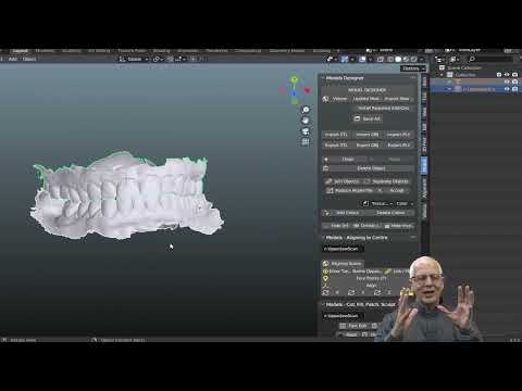
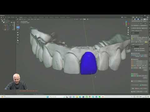
Blender is a 3D modeling application with tools for mesh editing, Boolean operations, and surface construction. In dentistry, it can be part of workflows for designing guides, anatomical models, and other devices, particularly when paired with specialized tools.
However, modeling an object that looks like a guide is not the same as producing a clinically safe device. The spatial relationships among the anatomy, planned prosthesis, implants, and instruments must be preserved.
Standard Blender should not be assumed to be validated medical software for implant treatment planning. Dental add-ons can simplify certain operations, but their features, indications, and conditions of use must be verified individually.
This tutorial outlines the workflow and verification criteria. It is not a universal set of parameters and does not replace training in guided surgery, system documentation, or professional responsibility.
Read also: Digital Dentistry Courses: How to Choose the Right Training · Dental Implant Planning Software Comparison · Nemoscan: Features for Implant Planning and Surgical Guides
Before Designing: Data Required for the Surgical Guide
The guide should translate a treatment plan driven by the prosthetic restoration and anatomical conditions into a physical device. That is why design begins before modeling.
Scanning, CBCT, and Prosthetic Planning
Organize the following elements:
- An intraoral scan or digitized model with sufficient coverage of the support area.
- CBCT data in DICOM format, when indicated for treatment planning.
- A diagnostic wax-up or digital prosthetic proposal.
- Implant positions and their corresponding axes, approved by the treating clinician.
- The selected support type and any need for additional fixation.
- Technical documentation for the guided surgery kit and sleeves, when used.
For patients, an important distinction is that scanning primarily captures surfaces, while CBCT allows evaluation of internal structures. One examination does not automatically replace the other.
Registration Between Surfaces and Anatomy
Alignment between the scan and CBCT data is critical. A surface that appears well aligned in one view may show discrepancies in another region.
Registration should be checked in multiple planes and reference areas, accounting for artifacts, restorations, and image quality. This evaluation usually takes place in the planning environment before transfer to the modeling software.
Do not try to compensate for questionable registration by moving only the guide in Blender. This may visually improve the fit while disrupting the correct relationship with the planned implants.
Step 1: Set Up Blender and Verify Scale
Create a dedicated file for the case and retain a copy of the original data. Organize objects into collections, such as anatomy, prosthesis, planning, sleeves, and guide.
This organization makes review easier and reduces the risk of editing the wrong structure.
Project Units and Dimensions
Establish the project's unit convention and confirm the imported dimensions. STL files do not carry reliable unit information, so scale interpretation depends on the applications involved.
Check a known distance in both the source file and Blender. Simply selecting “millimeters” in the interface is not enough: the actual dimensions of the geometry must match the case.
Before performing scale-dependent operations, check object transforms and apply them when appropriate for the method being used. Avoid resizing individual components after establishing the spatial relationship of the assembly.
Step 2: Import Meshes Without Losing Coordinates
Import the anatomical surfaces, prosthetic plan, and available reference elements. Depending on the source software, formats such as STL, OBJ, or PLY may be used.
Whenever possible, export objects using the same coordinate system. Do not manually reposition each file to make them “look aligned.”
After importing, check:
- Alignment between reference surfaces.
- The orientation of the implant axes.
- Component positions relative to the prosthetic proposal.
- The absence of mirroring or changes in scale.
- Correct identification of each object.
Importing only a cylinder representing the implant may be insufficient. The design requires unambiguous references for the axis, position, and height of the guiding components.
Step 3: Inspect and Prepare the Support Mesh
The surface that will support the guide must accurately represent the clinical condition. Missing areas, artifacts, or inappropriate automatic reconstructions can compromise fit.
Cleanup Without Altering Relevant Anatomy
Remove isolated mesh islands and elements unrelated to the case. Inspect for duplicate faces, inverted normals, self-intersections, and disconnected areas.
Holes in support areas should not be closed automatically as though the reconstructed surface were actual anatomy. Depending on the size and location of the defect, a new scan may be necessary.
Avoid aggressive smoothing in seating areas. Polygon reduction must also preserve details relevant to retention and stability.
Not every anatomical mesh needs to be closed. The final guide intended for fabrication, however, must form a coherent volume suitable for processing.
Step 4: Define Support, Extension, and Path of Insertion
Before adding thickness, define the area the guide will occupy. This decision depends on the distribution of support, surgical access, tissue conditions, and the ability to achieve unambiguous seating.
| Support type | Primary design consideration | Validation considerations |
|---|---|---|
| Tooth-supported | Distribute contact over appropriate surfaces | Interferences, tooth mobility, and recent restorations |
| Mucosa-supported | Account for the surface and stabilization protocol | Tissue compressibility and displacement |
| Bone-supported | Relate support to the anticipated exposed anatomy | Segmentation and surgical access |
| Combined support | Coordinate different support regions | Conflicting contacts and rocking |
Undercuts and Relief in the Surgical Guide
Evaluate undercuts relative to the path of insertion. A guide may closely match the teeth digitally yet still fail to seat in the mouth.
Undercut blockout and relief should preserve stability without creating binding. Fit clearance depends on the fabrication workflow, material, equipment, and validation performed.
There is no universal clearance value that works for every printer or resin. Parameters from another laboratory should not be copied without verifying the results in your own process.
Step 5: Build the Guide Body in Blender
Once the support area is defined, create an internal surface compatible with the intended seating. Then build the external volume and connect the boundaries to form the guide body.
Surface extraction, offset, extrusion, and modifiers such as Solidify can be used at this stage. The choice depends on mesh quality and the tools available.
Thickness, Edges, and Structural Strength
Automatically generating thickness does not guarantee a suitable device. Curved or narrow regions may develop self-intersections, uneven walls, and weak areas.
Pay particular attention to:
- Continuity between support regions.
- Thickness around the sleeve housings.
- Transitions between bulky and narrow sections.
- Edge finishing near tissues.
- The ability to insert and remove the guide without excessive deformation.
Dimensional limits must follow the validated material, process, and application. Excessively thin edges and unsupported extensions should be reviewed before proceeding.
Step 6: Position Sleeves and Guide Channels
This stage connects guide design with clinical instrumentation. The housing must maintain the planned axis and the vertical position required by the system.
Compatibility With the Guided Surgery Kit
Confirm the following in the manufacturer's documentation:
- Sleeve dimensions and geometry.
- The relationship among the sleeve, drill keys or reducers, and drills.
- References used for depth control.
- The specified distance between the sleeve and the implant reference.
- The sleeve installation and retention method.
- Restrictions on use and processing.
Terms such as “offset” may refer to distances measured between different reference points. Record which surfaces or points are being used rather than transferring only a number between programs.
Boolean Operations in Blender
One modeling strategy uses additive volumes to reinforce the housings and subtractive volumes to create their channels. Boolean operations must preserve the axis, height, and functional geometry.
Review the mesh after each operation. Internal faces, small fragments, and discontinuous walls can appear even when the exterior looks correct.
Do not derive dimensions solely from product images. Systems without metal sleeves also require specific compatibility and validation; removing the sleeve is not a neutral modification.
Step 7: Add Inspection Windows and Check Access
Inspection windows allow visualization of seating points. They should be placed where they provide useful clinical information without weakening the guide.
Openings may also improve visibility and surgical access, depending on the design. However, adding cutouts indiscriminately reduces rigidity.
Evaluate the space required for instruments, keys, and components. A design that looks correct on screen may be impractical because of limited mouth opening or interference with opposing teeth.
When additional fixation is needed, its trajectory must be planned and validated relative to the anatomy. Fixation elements should not be added solely as a geometric solution for stability.
Step 8: Validate the Surgical Guide Before Exporting
The review must distinguish file integrity from clinical suitability. An error-free mesh does not prove that the guide has been planned correctly.
Digital Checklist
- Scale and coordinates preserved.
- Path of insertion compatible with the support.
- Internal surface free of unintended changes.
- Thicknesses and connections reviewed.
- Sleeves aligned with the approved plan.
- Housings compatible with the selected system.
- Windows without evident structural compromise.
- Final volume free of self-intersections or loose elements.
Mesh analysis tools can help identify defects, but they do not replace professional review. When possible, compare the final guide with the treatment plan in the original planning environment.
Identify the approved version and maintain file traceability. Subsequent changes to implant positions, support, or the guided surgery system require another design review.
Step 9: Export, Fabricate, and Inspect the Guide
Export only the objects needed for fabrication. Reopen the exported file to check dimensions, orientation, and integrity before sending it for processing.
Printing must use a material indicated for the application and compatible with the equipment and protocol. Orientation, supports, washing, post-curing, and processing for clinical use must follow the applicable instructions.
Avoid supports on critical fitting surfaces whenever the process allows. Do not assume that any clear resin is suitable for surgical guides or that every sterilization method is compatible.
Inspect the fabricated guide for surface finish, sleeve installation, stability, and seating according to the clinical protocol. A model try-in can help, but it does not replace evaluation in the patient. Unexpected resistance, rocking, or incomplete seating requires investigation, not indiscriminate grinding.
In Clinical Practice
In Dr. Welson Pimentel's clinical approach, which combines implant dentistry, prosthodontics, and digital planning, the guide must be understood as part of a restorative treatment rather than an isolated device.
This perspective leads to three questions: Does the plan support the intended prosthesis? Does the support allow the planned position to be reproduced? Can the guide–instrument assembly be used under the patient's actual clinical conditions?
A useful review sequence is to check seating first, then the relationship with the instruments, and finally correspondence with the approved plan. If the support is incorrect, geometrically well-positioned sleeves will not solve the problem.
The greatest value of the digital workflow lies in its ability to document decisions, identify incompatibilities, and review the case before fabrication. Quality depends not only on mastering software commands but also on recognizing when the available data cannot support a reliable design.
Have questions about your treatment? Book an assessment at Dr. Welson Pimentel’s dental practice in Botafogo, Rio de Janeiro, to discuss your needs and care options. Visit the dental practice
Conclusion
Designing a surgical guide in Blender requires organized data, modeling proficiency, and clinical validation criteria. The complete workflow begins with prosthetic and anatomical planning, continues through support and guide channel design, and ends with inspection of the fabricated device.
Blender can contribute to this process when used within a technically validated workflow compatible with the clinical application. To discuss case feasibility or structure your digital planning workflow, consider speaking with Dr. Welson Pimentel and the Planejamento Express team.
Frequently asked questions
Can I design a surgical guide in the free version of Blender?
Blender provides modeling tools capable of building a guide's geometry. However, the base software should not be assumed to be a validated medical solution: treatment planning, instrument compatibility, and fabrication must be part of a workflow suitable for clinical use.
Do I need Blender for Dental to design the guide?
It is not required for general modeling operations. Dental add-ons may simplify certain steps, but you need to verify which features are available in the module and version being used, as well as their conditions of use.
What clearance should I use on the guide's internal surface?
There is no universal clearance. The parameter depends on the support geometry, material, equipment, and post-processing, and must be defined and verified within the fabrication workflow being used.
How do I set the sleeve height in Blender?
The position must reproduce the planning references and the guided system's specifications. Check the relationship among the sleeve, instruments, and depth control rather than transferring offset values between systems with different reference points.
Can I print the guide with any clear resin?
No. The material must be indicated for the application and used with compatible equipment and processing. Transparency alone does not establish biocompatibility, dimensional stability, or suitability for sterilization.
Does mesh analysis guarantee that the guide is ready for use?
No. It helps identify geometric defects, but it does not independently verify anatomical planning, clinical seating, or instrument compatibility. Approval requires professional review and inspection of the fabricated guide.
Dental care in Botafogo · Rio de Janeiro
Your smile deserves personalized care
Talk to Dr. Welson Pimentel about implants, prosthetics and oral health. An assessment is the first step toward understanding the right care for you.
- ✓ Dental implants
- ✓ Dental prosthetics
- ✓ Oral health